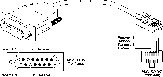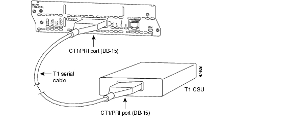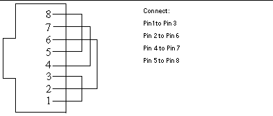

- PRI LOOPBACK CABLE PINOUT INSTALL
- PRI LOOPBACK CABLE PINOUT SERIAL
Note: During loss of power or whenever the MAX restarts, a relay closure returns the T1 PRI In accordance with requirements of AT&T Pub 62411 Pulse Density and Consecutive Zeros Enforcement For more information, see the MAX Reference Guide. You configure this parameter during installation. Your carrier determines the correct setting for the line buildout setting of the CSU. You must connect the port to other equipment that provides the interface to the WAN, such as an external CSU.
 If you disable the internal CSU on a T1/PRI port, you cannot connect directly to the WAN. The MAX unit's internal CSUs are compatible with dry-loop T1/PRI lines, and with span-powered or wet-loop powered T1/PRI lines. If you disconnect or turn off the MAX without prior notification, the carrier might temporarily discontinue your T1/PRI service.
 PRI LOOPBACK CABLE PINOUT INSTALL
Once you install the MAX, you must notify the carrier before disconnecting the MAX from the WAN. To avoid harming the WAN, you must contact your carrier for approval before installation.
If you enable the internal CSU on a T1/PRI port, you can connect the port directly to the metallic interface of the WAN. Disable the internal CSU by setting Front End to DSX. Enable the internal CSU by setting the Net/T1 > Line Config > Line N > Front End parameter to CSU. Your requirements differ depending on whether or not you enable the internal CSU on each T1/PRI port on the MAX. This section provides the specifications for the MAX unit's T1/PRI interface and covers cabling requirements. Use one of the following cables:100BASE-T2, 100BASE-T4 (not very popular), 100BASE-TX, or 100BASE-FX. Use an EIA/TIA 568 or IEEE 802.3 10Base-T cable. You need a twisted-pair Ethernet cable and a dual twisted-pair cable terminated with RJ-45 modular jacks. To install the Ethernet interface, you must have either of the equipment described in the sections below. The Ethernet address used to identify the Ethernet interface resides in the MAX unit's motherboard. 100 Base-T: 100 Mbits/s Baseband Modulation on Twisted Pair. 10Base-T (Unshielded Twisted Pair): Twisted pair Ethernet and IEEE 802.3 (10Base-T) with an RJ-45 connector, labeled LAN UTP. It provides a single Ethernet interface that auto-senses the Ethernet type to which it is connected. The base unit of a MAX has an Ethernet interface that supports the physical specifications of IEEE 802.3 and IEEE 802.14 with Ethernet 2 (Ethernet/DIX) framing. Part number 2510-0088-001 Signal (MAX) MAX RJ12 pin number VT-100 female DE-9 pin number Control Monitor and MIF Palmtop port and cabling pinouts Control Monitor and MIF Palmtop port and cable Palmtop port cabling pinouts for a Control Monitor Table C-3 lists the specifications you need to adapt the Palmtop port for use as a Control Monitor or MIF interface through a vt-100 terminal.įigure C-1. Note: O is Out (from the MAX toward the Palmtop). Pinouts for the Palmtop Controller Table C-2 specifies the pins and corresponding functions of the Palmtop Controller jacks. Note: *Pin 9 is not active (Ring Indication signal not supplied). 

Control Monitor and MIF Control port and cabling pinoutsĭE-9 pin number RS-232 signal name Function I/O Table C-1 lists all MAX models that use the RS-232 pinouts.
PRI LOOPBACK CABLE PINOUT SERIAL
The Control port uses a standard DE-9 female connector that conforms to the EIA RS-232 standard for serial interfaces. This section covers cabling pinouts for the Control Monitor, Palmtop Controller, and MIF interfaces.Ĭontrol port and cabling pinouts for the Control Monitor and MIF This appendix describes specifications for different facets of the MAX, and discusses cabling requirements.


 0 kommentar(er)
